目标
- 创建纹理
- 实现纹理采样
- 实现二次线性滤波
- 实现纹理地址包裹
- 实现读取图片数据作为纹理
参考资料:
- OpenGL ES学习笔记(三)——纹理
- LearnOpenGL中文 第7章 纹理
- 纹理的滤波方式
- 纹理采样和过滤
- Mipmap与纹理过滤
- 纹理 放大缩小过滤
- 【图像缩放篇之一】近邻取样插值和其速度优化
- 【图像缩放篇之二】二次线性插值和三次卷积插值
- 【图像缩放篇之三】三次线性插值和MipMap链
实现
定义Texture
创建Texture类,它的主要作用是保存一幅图片数据,并提供sample2d方法,用于在fragmentShader中提供纹理采样。
package net.jmecn.material;

import net.jmecn.math.ColorRGBA;
import net.jmecn.math.Vector2f;
import net.jmecn.math.Vector4f;
import net.jmecn.renderer.Image;

/**
 * 纹理
 *
 * @author yanmaoyuan
 *
 */
public class Texture {

    private int width;
    private int height;
    private byte[] components;

    public Texture(Image image) {
        setImage(image);
    }

    /**
     * 设置图像
     * @param image
     */
    public void setImage(Image image) {
        this.width = image.getWidth();
        this.height = image.getHeight();
        this.components = image.getComponents();
    }

    /**
     * 根据UV进行采样
     *
     * @param uv
     * @return
     */
    public Vector4f sample2d(Vector2f uv) {
        return new Vector4f(0);
    }

}
为了便于使用,额外提供一个构造方法,将生成一个8x8的黑白相间图片。注意这里的黑色是纯黑,ALPHA通道的值也为0。
/**
 * 默认纹理,生成一个网格黑白相间的网格。
 */
public Texture() {
    Image image = new Image(64, 64);

    // 创建一个ImageRaster用来画图。
    ImageRaster raster = new ImageRaster(image);

    // 底色填充为白色
    raster.fill(ColorRGBA.WHITE);

    // 纯黑
    ColorRGBA color = new ColorRGBA(0x00000000);
    for (int y = 0; y < 64; y++) {
        for (int x = 0; x < 64; x++) {
            int i = x / 8;
            int j = y / 8;
            if ((i + j) % 2 == 0) {
                raster.drawPixel(x, y, color);
            }
        }
    }

    setImage(image);
}
在Material中添加Texture成员,并提供get/set方法。
package net.jmecn.material;

/**
 * 材质
 *
 * @author yanmaoyuan
 *
 */
public class Material {

    protected Texture texture;
    protected RenderState renderState;

    public Material() {
        renderState = new RenderState();
    }

    public Texture getTexture() {
        return texture;
    }

    public void setTexture(Texture texture) {
        this.texture = texture;
    }

    public RenderState getRenderState() {
        return renderState;
    }

    public void setRenderState(RenderState renderState) {
        this.renderState = renderState;
    }

}
最邻近点采样
下面需要实现sample2d方法,先采用最邻近点采样。
创建getColor方法,用于从components中提取颜色,并保存为Vector4f()。
private final static float INV_SCALE = 1f / 255f;

/**
 * 提取颜色
 * @param x
 * @param y
 * @return
 */
public Vector4f getColor(int x, int y) {
    Vector4f color = new Vector4f();

    int index = (x + y * width) * 4;
    float r = (float)(0xFF & components[index]) * INV_SCALE;
    float g = (float)(0xFF & components[index+1]) * INV_SCALE;
    float b = (float)(0xFF & components[index+2]) * INV_SCALE;
    float a = (float)(0xFF & components[index+3]) * INV_SCALE;

    color.set(r, g, b, a);
    return color;
}
实现最邻近点采样。
/**
 * 最邻近点(NEAREST)采样
 *
 * @param s
 * @param t
 * @return
 */
protected Vector4f nearest(float s, float t) {

    // 计算坐标
    float u = (float) (width - 1) * s;
    float v = (float) (height - 1) * (1 - t);

    // 取整
    int iu = (int) u;
    int iv = (int) v;

    Vector4f color = getColor(iu, iv);
    return color;
}

/**
 * 根据UV进行采样
 *
 * @param uv
 * @return
 */
public Vector4f sample2d(Vector2f uv) {
    return nearest(uv.x, uv.y);
}
像素着色
SoftwareRaster中的fragmengShader终于有用武之地了。
在fragmengShader方法中进行纹理采样,并把纹理的颜色和原本的顶点颜色融合在一起。
/**
 * 片段着色器
 * @param frag
 */
private void fragmentShader(RasterizationVertex frag) {
    Texture texture = renderer.getMaterial().getTexture();
    if (texture != null && frag.hasTexCoord) {
        Vector4f texColor = texture.sample2d(frag.texCoord);
        frag.color.multLocal(texColor);
    }
}
测试用例
为了便于测试纹理,我先创建了一个四边形网格。它的中心位于模型空间的原点,正面朝向Z轴正方向。
package net.jmecn.scene.shape;

import net.jmecn.math.Vector2f;
import net.jmecn.math.Vector3f;
import net.jmecn.math.Vector4f;
import net.jmecn.scene.Mesh;
import net.jmecn.scene.Vertex;

/**
 * 四边形网格。
 * @author yanmaoyuan
 *
 */
public class Quad extends Mesh {

    public Quad() {

        // 顶底位置
        float[] positions = {
                -1, -1,  0,
                 1, -1,  0,
                 1,  1,  0,
                -1,  1,  0
        };

        // 顶点颜色
        float[] colors = {
                1, 1, 0, 1,
                0, 1, 1, 1,
                1, 0, 1, 1,
                1, 1, 1, 1
        };

        // 纹理坐标
        float[] texCoords = {
                0, 0,
                1, 0,
                1, 1,
                0, 1
        };

        // 顶点法线
        float[] normals = {
                0, 0, 1,
                0, 0, 1,
                0, 0, 1,
                0, 0, 1
        };

        // 顶点索引
        this.indexes = new int[]{
                0, 1, 2,
                0, 2, 3
        };

        this.vertexes = new Vertex[positions.length];

        for(int i = 0; i < indexes.length; i++) {
            int index = indexes[i];

            vertexes[index] = new Vertex();
            vertexes[index].position = new Vector3f( positions[index*3], positions[index*3+1], positions[index*3+2]);
            vertexes[index].normal = new Vector3f( normals[index*3], normals[index*3+1], normals[index*3+2]);
            vertexes[index].color = new Vector4f( colors[index*4], colors[index*4+1], colors[index*4+2], colors[index*4+3]);
            vertexes[index].texCoord = new Vector2f(texCoords[index*2], texCoords[index*2+1]);
        }
    }
}
然后编写测试代码如下:
package net.jmecn.examples;

import net.jmecn.Application;
import net.jmecn.material.Material;
import net.jmecn.material.Texture;
import net.jmecn.math.Vector3f;
import net.jmecn.scene.Geometry;
import net.jmecn.scene.shape.Quad;

/**
 * 测试纹理采样效果
 * @author yanmaoyuan
 *
 */
public class Test3DTexture extends Application {

    public static void main(String[] args) {
        Test3DTexture app = new Test3DTexture();
        app.setResolution(400, 300);
        app.setTitle("Test Texture");
        app.setFrameRate(60);
        app.start();
    }

    @Override
    protected void initialize() {
        // 初始化摄像机
        getCamera().lookAt(new Vector3f(1, 2, 3),
                Vector3f.ZERO, Vector3f.UNIT_Y);

        // 定义材质
        Material material = new Material();

        // 使用程序纹理
        Texture texture = new Texture();
        material.setTexture(texture);

        // 添加到场景中
        Geometry geom = new Geometry(new Quad(), material);
        rootNode.attachChild(geom);
    }

    @Override
    protected void update(float delta) {}

}
运行程序,效果如下:
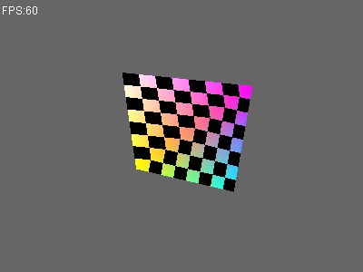
可以看到,使用最邻近点(Nearest)算法进行纹理采样,像素边缘都明显的锯齿。其次,由于没有进行对纹理坐标进行透视校正,两个三角形各自使用仿射(Affine)变换来处理纹理坐标,导致纹理有些变形。
透视校正的问题,晚点再处理。下面继续实现另一种纹理采样方法。
双线性纹理采样
在Texture类中,实现bilinear采样算法。
/**
 * 二次线性(Bilinear)采样
 *
 * @param s
 * @param t
 * @return
 */
protected Vector4f bilinear(float s, float t) {
    // 计算坐标
    float u = (float) (width - 1) * s;
    float v = (float) (height - 1) * (1 - t);

    // 取整
    int iu0 = (int) u;
    int iv0 = (int) v;

    int iu1 = iu0 + 1;
    int iv1 = iv0 + 1;

    if (iu1 > width - 1)
        iu1 = iu0;

    if (iv1 > height - 1)
        iv1 = iv0;

    // 四个采样点
    Vector4f c0 = getColor(iu0, iv0);
    Vector4f c1 = getColor(iu1, iv0);
    Vector4f c2 = getColor(iu0, iv1);
    Vector4f c3 = getColor(iu1, iv1);

    // 计算四个采样点的贡献值
    float du0 = u - iu0;
    float dv0 = v - iv0;
    float du1 = 1f - du0;
    float dv1 = 1f - dv0;

    // 计算最终的颜色
    c0.x = c0.x * du1 * dv1 + c1.x * du0 * dv1 + c2.x * du1 * dv0 + c3.x * du0 * dv0;
    c0.y = c0.y * du1 * dv1 + c1.y * du0 * dv1 + c2.y * du1 * dv0 + c3.y * du0 * dv0;
    c0.z = c0.z * du1 * dv1 + c1.z * du0 * dv1 + c2.z * du1 * dv0 + c3.z * du0 * dv0;
    c0.w = c0.w * du1 * dv1 + c1.w * du0 * dv1 + c2.w * du1 * dv0 + c3.w * du0 * dv0;

    return c0;
}
现在有两种采样算法,我们需要一个参数来决定如何进行采样。我们暂时不考虑纹理缩小时的MinFilter、MinMap、各向异性等算法,只区分最邻近采样和二次线性采样算法。
在Texture类中定义MagFilter枚举,并根据它的值来决定如何采样。
/**
 * 纹理放大时,如何滤波
 */
public enum MagFilter {
    NEAREST,    // 最邻近
    BILINEAR,   // 二次线性滤波
}

private MagFilter magFilter = MagFilter.BILINEAR;

/**
 * 设置放大滤波方式
 * @param magFilter
 */
public void setMagFilter(MagFilter magFilter) {
    this.magFilter = magFilter;
}

/**
 * 根据UV进行采样
 *
 * @param uv
 * @return
 */
public Vector4f sample2d(Vector2f uv) {
    switch (magFilter) {
    case NEAREST:
        return nearest(uv.x, uv.y);
    case BILINEAR:
        return bilinear(uv.x, uv.y);
    }

    return new Vector4f(0);
}
再次执行测试用例,结果如下:
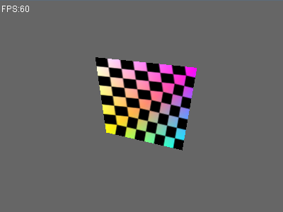
可以看出,相比于最邻近点采样,黑白色块的边缘比较平滑。
纹理包裹模式
纹理坐标通常的范围是从(0, 0)到(1, 1),如果我们把纹理坐标设置为范围以外会发生什么?
定义WarpMode枚举类型,用来描述不同的包裹方式:
- REPEAT:纹理的默认行为。重复纹理图像。
- MIRRORED_REPEAET:和REPEAT一样,除了重复的图片是镜像放置的。
- CLAMP_TO_EDGE:纹理坐标会在0到1之间。超出的部分会重复纹理坐标的边缘,就是边缘被拉伸。
- CLAMP_TO_BORDER:超出的部分是用户指定的边缘的颜色。
在Texture类中添加代码如下:
/**
 * 纹理包围模式
 */
public enum WarpMode {
    REPEAT,             // 纹理的默认行为。重复纹理图像。
    MIRRORED_REPEAT,    // 和REPEAT一样,除了重复的图片是镜像放置的。
    CLAMP_TO_EDGE,      // 纹理坐标会在0到1之间。超出的部分会重复纹理坐标的边缘,就是边缘被拉伸。
    CLAMP_TO_BORDER     // 超出的部分是用户指定的边缘的颜色。
}

/**
 * 指定包围模式属于哪个轴
 */
public enum WarpAxis {
    S, T
}

private WarpMode warpS = WarpMode.REPEAT;
private WarpMode warpT = WarpMode.REPEAT;
private Vector4f borderColor = new Vector4f(0);

/**
 * 设置纹理包裹模式
 * @param mode
 */
public void setWarpMode(WarpMode mode) {
    warpS = mode;
    warpT = mode;
}

/**
 * 设置纹理包裹模式
 * @param axis
 * @param mode
 */
public void setWarpMode(WarpAxis axis, WarpMode mode) {
    switch (axis){
    case S:
        warpS = mode;
        break;
    case T:
        warpT = mode;
    }
}

/**
 * 设置边框颜色
 * @param borderColor
 */
public void setBorderColor(Vector4f borderColor) {
    this.borderColor = borderColor;
}
然后,实现纹理坐标处理。
/**
 * 根据UV进行采样
 *
 * @param uv
 * @return
 */
public Vector4f sample2d(Vector2f uv) {
    float s = uv.x;
    float t = uv.y;

    if (s < 0 || s > 1 || t < 0 || t > 1) {
        if (warpS == WarpMode.CLAMP_TO_BORDER || warpT == WarpMode.CLAMP_TO_BORDER) {
            return borderColor;
        }

        s = warp(s, warpS);
        t = warp(t, warpT);
    }

    switch (magFilter) {
    case NEAREST:
        return nearest(s, t);
    case BILINEAR:
        return bilinear(s, t);
    }

    return new Vector4f(0);
}

/**
 * 纹理坐标包裹
 * @param value
 * @param mode
 * @return
 */
private float warp(float value, WarpMode mode) {
    switch (mode) {
    case REPEAT: {
        // 整数部分
        int n = (int) value;
        // 小数部分
        float frac = value - n;

        if (frac < 0) {
            frac = frac + 1f;
        }
        value = frac;
        break;
    }
    case MIRRORED_REPEAT: {
        // 整数部分
        int n = (int) value;
        // 小数部分
        float frac = value - n;

        if (frac < 0) {
            frac = - frac;
        }

        if (n % 2 != 0) {
            frac = 1 - frac;
        }

        value = frac;
        break;
    }
    case CLAMP_TO_EDGE:
        if (value < 0) {
            value = 0;
        }
        if (value > 1) {
            value = 1;
        }
        break;
    case CLAMP_TO_BORDER:
        break;
    }
    return value;
}
测试纹理包裹模式
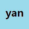
先制作一张图片,命名为yan.bmp。在工程目录下创建res文件夹,把yan.bmp文件放进去。
读取图片
在Image类中,增加读取图片的代码。使用ImageIO将图片文件读取为BufferedImage,然后把数据写入Image类的components数组中。
public Image(String fileName) throws IOException {
    int width = 0;
    int height = 0;
    byte[] components = null;

    BufferedImage image = ImageIO.read(new File(fileName));

    width = image.getWidth();
    height = image.getHeight();

    int imgPixels[] = new int[width * height];
    image.getRGB(0, 0, width, height, imgPixels, 0, width);
    components = new byte[width * height * 4];

    for(int i = 0; i < width * height; i++) {
        int pixel = imgPixels[i];

        components[i * 4]     = (byte)((pixel >> 16) & 0xFF); // R
        components[i * 4 + 1] = (byte)((pixel >> 8 ) & 0xFF); // G
        components[i * 4 + 2] = (byte)((pixel      ) & 0xFF); // B
        components[i * 4 + 3] = (byte)((pixel >> 24) & 0xFF); // A
    }

    this.width = width;
    this.height = height;
    this.components = components;
}
编写测试代码
编写一个新的测试用例,故意把纹理坐标写成[0, 1]之外的值。把S轴的WarpMode设为REPEAT,T轴的WarpMode设为MIRRORED_REPEAT。
package net.jmecn.examples;

import java.io.IOException;

import net.jmecn.Application;
import net.jmecn.material.Material;
import net.jmecn.material.Texture;
import net.jmecn.material.Texture.WarpAxis;
import net.jmecn.material.Texture.WarpMode;
import net.jmecn.math.Vector2f;
import net.jmecn.math.Vector3f;
import net.jmecn.math.Vector4f;
import net.jmecn.renderer.Image;
import net.jmecn.scene.Geometry;
import net.jmecn.scene.Mesh;

/**
 * 测试纹理采样效果
 * @author yanmaoyuan
 *
 */
public class Test3DWarpMode extends Application {

    public static void main(String[] args) {
        Test3DWarpMode app = new Test3DWarpMode();
        app.setResolution(400, 300);
        app.setTitle("Test Texture");
        app.setFrameRate(60);
        app.start();
    }

    @Override
    protected void initialize() {
        // 初始化摄像机
        getCamera().lookAt(new Vector3f(1, 2, 3),
                Vector3f.ZERO, Vector3f.UNIT_Y);

        // 定义材质
        Material material = new Material();

        try {
            Image image = new Image("res/yan.bmp");
            Texture texture = new Texture(image);
            texture.setBorderColor(new Vector4f(0));
            texture.setWarpMode(WarpAxis.S, WarpMode.REPEAT);
            texture.setWarpMode(WarpAxis.T, WarpMode.MIRRORED_REPEAT);
            material.setTexture(texture);
        } catch (IOException e) {
            e.printStackTrace();
        }


        // 定义四边形网格
        Vector3f[] positions = {
            new Vector3f(0, 0, 0),
            new Vector3f(1, 0, 0),
            new Vector3f(1, 1, 0),
            new Vector3f(0, 1, 0),
        };
        Vector3f[] normals = {
            new Vector3f(0, 0, 1),
            new Vector3f(0, 0, 1),
            new Vector3f(0, 0, 1),
            new Vector3f(0, 0, 1),
        };
        Vector4f[] colors = {
            new Vector4f(1),
            new Vector4f(1),
            new Vector4f(1),
            new Vector4f(1),
        };
        Vector2f[] texCoords = {
            new Vector2f(-2, -2),
            new Vector2f(2, -2),
            new Vector2f(2, 2),
            new Vector2f(-2, 2),
        };
        int[] indexes = {
            0, 1, 2,
            0, 2, 3,
        };

        Mesh mesh = new Mesh(positions, indexes, texCoords, normals, colors);

        // 添加到场景中
        Geometry geom = new Geometry(mesh, material);
        rootNode.attachChild(geom);
    }

    @Override
    protected void update(float delta) {}

}
运行程序,效果如下:
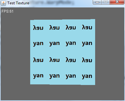
可以看到,水平方向(S轴)是直接重复出现相同纹理,垂直方向(T轴)则是像照镜像一样重复出现镜像纹理。
总结
目标达成。纹理坐标还需要做一些透视校正,这个留到后面再做。