目标
- 光栅化3D顶点
- 光栅化3D线段
- 光栅化3D线框三角形
- 光栅化3D实心三角形
- 实现顶点线性插值
实现
本章主要实现SoftwareRaster中对基本形状的光栅化。
计算空间变换矩阵
Renderer中定义了诸多空间变换矩阵,在渲染之前先要把它们初始化。
private Matrix4f worldMatrix = new Matrix4f();
private Matrix4f viewMatrix = new Matrix4f();
private Matrix4f projectionMatrix = new Matrix4f();
private Matrix4f viewProjectionMatrix = new Matrix4f();
private Matrix4f worldViewMatrix = new Matrix4f();
private Matrix4f worldViewProjectionMatrix = new Matrix4f();
private Matrix4f viewportMatrix = new Matrix4f();
视口变换矩阵是在初始化渲染器时就计算好了的。只要窗口大小不变,就不需要重新计算。
/**
 * 初始化渲染器
 * @param width
 * @param height
 */
public Renderer(int width, int height) {
    image = new Image(width, height);
    raster = new SoftwareRaster(this, image);

    // 计算视口变换矩阵
    updateViewportMatrix(width, height);
}

/**
 * 视口变换矩阵
 */
public void updateViewportMatrix(float width, float height) {
    float w = width * 0.5f;
    float h = height * 0.5f;

    // 把模型移到屏幕中心,并且按屏幕比例放大。
    float m00 = w, m01 = 0,  m02 = 0,  m03 = w;
    float m10 = 0, m11 = -h, m12 = 0,  m13 = h;
    float m20 = 0, m21 = 0,  m22 = 1f, m23 = 0;
    float m30 = 0, m31 = 0,  m32 = 0,  m33 = 1;

    viewportMatrix.set(m00, m01, m02, m03, m10, m11, m12, m13, m20, m21, m22, m23, m30, m31, m32, m33);
}

/**
 * 视口变换矩阵
 */
public void updateViewportMatrix(float xmin, float ymin, float xmax, float ymax, float near, float far) {
    // 把模型移到屏幕中心,并且按屏幕比例放大。
    float m00 = (xmax - xmin) * 0.5f, m01 = 0,                     m02 = 0,                 m03 = (xmax + xmin) * 0.5f;
    float m10 = 0,                    m11 = -(ymax - ymin) * 0.5f, m12 = 0,                 m13 = (ymax + ymin) * 0.5f;
    float m20 = 0,                    m21 = 0,                     m22 = (far-near) * 0.5f, m23 = (far + near) * 0.5f;
    float m30 = 0,                    m31 = 0,                     m32 = 0,                 m33 = 1f;

    viewportMatrix.set(m00, m01, m02, m03, m10, m11, m12, m13, m20, m21, m22, m23, m30, m31, m32, m33);
}
观察变换矩阵 和 投影变换矩阵 在Camera中计算。当Renderer的render方法被调用时,要把camera中的观察变换矩阵、投影变换矩阵等复制到Renderer的对应成员中,便于渲染使用。
世界变换矩阵与Geometry的WorldTransform有关,应当在遍历每一个Geometry时计算。
/**
 * 渲染场景
 * @param scene
 * @param camera
 */
public void render(List<Geometry> geomList, Camera camera) {

    // 根据Camera初始化观察变换矩阵。
    viewMatrix.set(camera.getViewMatrix());
    projectionMatrix.set(camera.getProjectionMatrix());
    viewProjectionMatrix.set(camera.getViewProjectionMatrix());

    // TODO 剔除那些不可见的物体

    // 遍历场景中的Mesh
    for(int i=0; i<geomList.size(); i++) {
        Geometry geom = geomList.get(i);

        // 根据物体的世界变换,计算MVP等变换矩阵。
        worldMatrix.set(geom.getWorldTransform().toTransformMatrix());
        viewMatrix.mult(worldMatrix, worldViewMatrix);
        viewProjectionMatrix.mult(worldMatrix, worldViewProjectionMatrix);

        // TODO 使用包围体,剔除不可见物体

        // 渲染
        render(geom);
    }
}
顶点着色阶段
对于Geometry中的每个顶点,要调用vertexShader来对顶点进行空间变换和着色。
/**
 * 顶点着色
 * @param vert
 * @return
 */
protected RasterizationVertex vertexShader(Vertex vert) {
    RasterizationVertex out = new RasterizationVertex();
    // 顶点位置
    out.position.set(vert.position, 1f);
    // 顶点法线
    if (vert.normal != null) {
        out.normal.set(vert.normal);
        out.hasNormal = true;
    }
    // 纹理坐标
    if (vert.texCoord != null) {
        out.texCoord.set(vert.texCoord);
        out.hasTexCoord = true;
    }
    // 顶点颜色
    if (vert.color != null) {
        out.color.set(vert.color);
        out.hasVertexColor = true;
    }

    // 顶点着色器
    // 模型-观察-透视 变换
    worldViewProjectionMatrix.mult(out.position, out.position);

    return out;
}
由于现在还没有实现顶点光照,因此vertexShader并不需要做什么特别的事情,只需要把Vertex中的值复制到一个RasterizationVertex对象中,并使用worldViewProjectionMatrix矩阵将顶点位置变换到投影空间。
在render方法中遍历Geometry中的每个三角形,执行vertexShader,然后在观察空间中进行背面剔除。
/**
 * 渲染单个物体
 * @param geometry
 */
protected void render(Geometry geometry) {

    // 设置材质
    this.material = geometry.getMaterial();
    // 设置渲染状态
    this.raster.setRenderState(material.getRenderState());

    // 用于保存变换后的向量坐标。
    Vector3f a = new Vector3f();
    Vector3f b = new Vector3f();
    Vector3f c = new Vector3f();

    // 提取网格数据
    Mesh mesh = geometry.getMesh();
    int[] indexes = mesh.getIndexes();
    Vertex[] vertexes = mesh.getVertexes();

    // 遍历所有三角形
    for (int i = 0; i < indexes.length; i += 3) {

        Vertex v0 = vertexes[indexes[i]];
        Vertex v1 = vertexes[indexes[i+1]];
        Vertex v2 = vertexes[indexes[i+2]];

        // 执行顶点着色器
        RasterizationVertex out0 = vertexShader(v0);
        RasterizationVertex out1 = vertexShader(v1);
        RasterizationVertex out2 = vertexShader(v2);

        // 在观察空间进行背面消隐
        worldViewMatrix.mult(v0.position, a);
        worldViewMatrix.mult(v1.position, b);
        worldViewMatrix.mult(v2.position, c);

        if (cullBackFace(a, b, c))
            continue;

        // TODO 视锥裁剪


        raster.rasterizeTriangle(out0, out1, out2);
    }
}
然后,就进入了光栅化阶段。
光栅化像素
这个实现很简单,从frag参数中取出color的值,然后转成0~255的整数,保存到Image的components中。components在这里被当做了3D引擎中的帧缓存(FrameBuffer)。
注意:由于frag中的color是使用Vector4f来保存的,要调用clamp方法来把4个通道的值对齐到0.0 ~ 1.0之间,保证颜色的取值有意义。
/**
 * 光栅化点
 * @param x
 * @param y
 * @param frag
 */
public void rasterizePixel(int x, int y, RasterizationVertex frag) {

    if (x < 0 || y < 0 || x >= width || y >= height) {
        return;
    }

    // 执行片段着色器
    fragmentShader(frag);

    int index = (x + y * width) * 4;
    Vector4f destColor = frag.color;
    destColor.x = clamp(destColor.x, 0, 1);
    destColor.y = clamp(destColor.y, 0, 1);
    destColor.z = clamp(destColor.z, 0, 1);
    destColor.w = clamp(destColor.w, 0, 1);

    // TODO 深度测试

    // TODO Alpha测试

    // TODO 混色

    // TODO 写入depthBuffer

    // 写入frameBuffer
    components[index] = (byte)(destColor.x * 0xFF);
    components[index + 1] = (byte)(destColor.y * 0xFF);
    components[index + 2] = (byte)(destColor.z * 0xFF);
    components[index + 3] = (byte)(destColor.w * 0xFF);
}
光栅化3D线段
稍微修改一下ImageRaster中的drawLineBresenham代码,就变成了rasterizeLine方法。
/**
 * 光栅化线段,使用Bresenham算法。
 * @param v0
 * @param v1
 */
public void rasterizeLine(RasterizationVertex v0, RasterizationVertex v1) {
    int x = (int) v0.position.x;
    int y = (int) v0.position.y;

    int w = (int) (v1.position.x - v0.position.x);
    int h = (int) (v1.position.y - v0.position.y);

    int dx1 = w < 0 ? -1 : (w > 0 ? 1 : 0);
    int dy1 = h < 0 ? -1 : (h > 0 ? 1 : 0);

    int dx2 = w < 0 ? -1 : (w > 0 ? 1 : 0);
    int dy2 = 0;

    int fastStep = Math.abs(w);
    int slowStep = Math.abs(h);
    if (fastStep <= slowStep) {
        fastStep = Math.abs(h);
        slowStep = Math.abs(w);

        dx2 = 0;
        dy2 = h < 0 ? -1 : (h > 0 ? 1 : 0);
    }
    int numerator = fastStep >> 1;

    for (int i = 0; i <= fastStep; i++) {
        // 线性插值
        float t = (y - v0.position.y) / (v1.position.y - v0.position.y);
        RasterizationVertex frag = new RasterizationVertex();
        frag.interpolateLocal(v0, v1, t);
        rasterizePixel(x, y, frag);

        numerator += slowStep;
        if (numerator >= fastStep) {
            numerator -= fastStep;
            x += dx1;
            y += dy1;
        } else {
            x += dx2;
            y += dy2;
        }

        // 线性插值
        t = (y - v0.position.y) / (v1.position.y - v0.position.y);
        frag = new RasterizationVertex();
        frag.interpolateLocal(v0, v1, t);

        rasterizePixel(x, y, frag);
    }
}
对于线段中的每一个像素,使用 t = (y-v0.position.y) / (v1.position.y - v0.position.y)来进行线性插值,可以得到每个像素的颜色。
但是这种算法是有问题的,因为没有考虑线段为水平线的情况。当直线的斜率小于1时,最好使用 t = (x-v0.postion.x) / (v1.position.x - v0.position.x) 来插值。
不过,说实话这个问题影响不大,待会写个测试用例来感受一下。
光栅化线框三角形
这个操作非常简单。先用透视除法把三个顶点变换到投影空间(x/w. y/w. z/w, 1),然后利用视口变换矩阵把顶点位置修正到屏幕空间,最后画三条线段。
/**
 * 光栅化三角形
 * @param v0
 * @param v1
 * @param v2
 */
public void rasterizeTriangle(RasterizationVertex v0, RasterizationVertex v1, RasterizationVertex v2) {

    // 将顶点变换到投影平面
    v0.perspectiveDivide();
    v1.perspectiveDivide();
    v2.perspectiveDivide();

    Matrix4f viewportMatrix = renderer.getViewportMatrix();

    // 把顶点位置修正到屏幕空间。
    viewportMatrix.mult(v0.position, v0.position);
    viewportMatrix.mult(v1.position, v1.position);
    viewportMatrix.mult(v2.position, v2.position);

    rasterizeLine(v0, v1);
    rasterizeLine(v0, v2);
    rasterizeLine(v1, v2);

}
测试线框三角形
立方体网格
为了方便后续的测试,我定义了一个立方体网格,它的中心位于模型空间的原点,每个点都有不同的顶点颜色。
代码如下:
package net.jmecn.scene.shape;

import net.jmecn.math.Vector2f;
import net.jmecn.math.Vector3f;
import net.jmecn.math.Vector4f;
import net.jmecn.scene.Mesh;
import net.jmecn.scene.Vertex;

/**
 * 立方体网格
 * @author yanmaoyuan
 *
 */
public class Box extends Mesh {

    public Box() {

        // 顶点坐标
        float[] positions = {
                // back
                 1,-1,-1,  -1,-1,-1,   1, 1,-1,  -1, 1,-1,
                // front
                -1,-1, 1,   1,-1, 1,  -1, 1, 1,   1, 1, 1,
                // left
                 1,-1, 1,   1,-1,-1,   1, 1, 1,   1, 1,-1,
                // right
                -1,-1,-1,  -1,-1, 1,  -1, 1,-1,  -1, 1, 1,
                // top
                -1, 1,-1,  -1, 1, 1,   1, 1,-1,   1, 1, 1,
                // bottom
                 1,-1,-1,   1,-1, 1,  -1,-1,-1,  -1,-1, 1,
        };

        // 顶点法线
        float[] normals = {
                // back
                0, 0,-1,   0, 0,-1,   0, 0,-1,   0, 0,-1,
                //front
                0, 0, 1,   0, 0, 1,   0, 0, 1,   0, 0, 1,
                // left
               -1, 0, 0,  -1, 0, 0,  -1, 0, 0,  -1, 0, 0,
                // right
                1, 0, 0,   1, 0, 0,   1, 0, 0,   1, 0, 0,
                // top
                0, 1, 0,   0, 1, 0,   0, 1, 0,   0, 1, 0,
                // bottom
                0,-1, 0,   0,-1, 0,   0,-1, 0,   0,-1, 0,
        };

        // 纹理坐标
        float[] texCoords = {
                // back
                0, 0,  1, 0,  0, 1,  1, 1,
                // front
                0, 0,  1, 0,  0, 1,  1, 1,
                // left
                0, 0,  1, 0,  0, 1,  1, 1,
                // right
                0, 0,  1, 0,  0, 1,  1, 1,
                // top
                0, 0,  1, 0,  0, 1,  1, 1,
                // bottom
                0, 0,  1, 0,  0, 1,  1, 1,
        };

        // 顶点颜色
        float[] colors = {
                // back
                1, 0, 0, 1,   0, 0, 0, 1,   1, 1, 0, 1,   0, 1, 0, 1,
                // front
                0, 0, 1, 1,   1, 0, 1, 1,   0, 1, 1, 1,   1, 1, 1, 1,
                // left
                1, 0, 1, 1,   1, 0, 0, 1,   1, 1, 1, 1,   1, 1, 0, 1,
                // right
                0, 0, 0, 1,   0, 0, 1, 1,   0, 1, 0, 1,   0, 1, 1, 1,
                // top
                0, 1, 0, 1,   0, 1, 1, 1,   1, 1, 0, 1,   1, 1, 1, 1,
                // bottom
                1, 0, 0, 1,   1, 0, 1, 1,   0, 0, 0, 1,   0, 0, 1, 1,
        };

        // 顶点索引
        this.indexes = new int[]{
                // back
                0, 1, 3,  0, 3, 2,
                // front
                4, 5, 7,  4, 7, 6,
                // left
                8, 9, 11, 8, 11, 10,
                // right
                12, 13, 15,  12, 15, 14,
                // top
                16, 17, 19, 16, 19, 18,
                // bottom
                20, 21, 23, 20, 23, 22,
        };

        this.vertexes = new Vertex[positions.length];

        for(int i = 0; i < indexes.length; i++) {
            int index = indexes[i];

            vertexes[index] = new Vertex();
            vertexes[index].position = new Vector3f( positions[index*3], positions[index*3+1], positions[index*3+2]);
            vertexes[index].normal = new Vector3f( normals[index*3], normals[index*3+1], normals[index*3+2]);
            vertexes[index].color = new Vector4f( colors[index*4], colors[index*4+1], colors[index*4+2], colors[index*4+3]);
            vertexes[index].texCoord = new Vector2f(texCoords[index*2], texCoords[index*2+1]);
        }
    }
}
测试用例
重构一下以前写的Test3DView代码:
package net.jmecn.examples;

import net.jmecn.Application;
import net.jmecn.material.Material;
import net.jmecn.math.Vector3f;
import net.jmecn.renderer.Camera;
import net.jmecn.scene.Geometry;
import net.jmecn.scene.Mesh;
import net.jmecn.scene.shape.Box;

/**
 * 测试3D观察的效果
 * @author yanmaoyuan
 *
 */
public class Test3DView extends Application {

    public static void main(String[] args) {
        Test3DView app = new Test3DView();
        app.setResolution(400, 300);
        app.setTitle("3D View");
        app.setFrameRate(60);
        app.start();
    }

    private Geometry geom;

    private final static float PI = 3.1415626f;
    private final static float _2PI = PI * 2;
    private float angle = 0;// 旋转角度

    @Override
    protected void initialize() {

        // 网格
        Mesh mesh = new Box();

        // 材质
        Material material = new Material();

        // 添加到场景中
        this.geom = new Geometry(mesh, material);
        rootNode.attachChild(geom);

        // 调整摄像机的位置
        Camera cam = getCamera();
        cam.lookAt(new Vector3f(3, 4, 8), Vector3f.ZERO, Vector3f.UNIT_Y);
    }

    @Override
    protected void update(float delta) {
        // 每秒旋转180°
        angle += delta * PI;

        // 若已经旋转360°,则减去360°。
        if (angle > _2PI) {
            angle -= _2PI;
        }

        // 计算旋转:绕Z轴顺时针方向旋转
        geom.getLocalTransform().getRotation().fromAxisAngle(Vector3f.UNIT_Y, -angle);
    }

}
运行结果:

还行。
光栅化实心三角形
与ImageRaster一样,先分别光栅化“平底三角形”和“平顶三角形”,用扫描线进行光栅化。然后把任意三角形分成“平顶三角形”和“平底三角形”,分别光栅化。
光栅化扫描线
这个过程跟使用Bresenham算法很像,只是不用关心斜率的问题了。
/**
 * 光栅化扫描线
 * @param v0
 * @param v1
 * @param y
 */
public void rasterizeScanline(RasterizationVertex v0, RasterizationVertex v1, int y) {
    int x0 = (int) Math.ceil(v0.position.x);
    // 按照DirectX和OpenGL的光栅化规则,舍弃右下的顶点。
    int x1 = (int) Math.floor(v1.position.x);

    for (int x = x0; x <= x1; x++) {
        if (x < 0 || x >= width)
            continue;

        // 线性插值
        // FIXME 需要透视校正
        float t = (x - v0.position.x) / (v1.position.x - v0.position.x);
        RasterizationVertex frag = new RasterizationVertex();
        frag.interpolateLocal(v0, v1, t);

        rasterizePixel(x, y, frag);
    }
}
注意:这个算法的实现是有坑的,需要注意避免重复光栅化相邻三角形的边。一般使用DirectX和OpenGL的规则,舍弃三角形“右下”边上的顶点。
我没有做Edge Equation,只是利用Math.ceil()函数对左顶点靠右取整,用Math.floor()函数对右顶点靠左取整,效果还不错。
光栅化平底三角形
/**
 * 画平底实心三角形
 * @param v0 上顶点
 * @param v1 底边左顶点
 * @param v2 底边右顶点
 */
private void fillBottomLineTriangle(RasterizationVertex v0, RasterizationVertex v1, RasterizationVertex v2) {
    int y0 = (int) Math.ceil(v0.position.y);
    int y2 = (int) Math.ceil(v2.position.y);

    for (int y = y0; y <y2; y++) {
        if (y >= 0 && y < this.height) {

            // 插值生成左右顶点
            // FIXME 需要透视校正
            float t = (y - v0.position.y) / (v1.position.y - v0.position.y);

            RasterizationVertex vl = new RasterizationVertex();
            vl.interpolateLocal(v0, v1, t);
            RasterizationVertex vr = new RasterizationVertex();
            vr.interpolateLocal(v0, v2, t);

            //扫描线填充
            rasterizeScanline(vl, vr, y);
        }
    }
}
光栅化平顶三角形
/**
 * 画平顶实心三角形
 * @param v0 顶边左顶点
 * @param v1 顶边右顶点
 * @param v2 下顶点
 */
private void fillTopLineTriangle(RasterizationVertex v0, RasterizationVertex v1, RasterizationVertex v2) {
    int y0 = (int) Math.ceil(v0.position.y);
    int y2 = (int) Math.ceil(v2.position.y);

    for (int y = y0; y < y2; y++) {
        if (y >= 0 && y < this.height) {
            // 插值生成左右顶点
            // FIXME 需要透视校正
            float t = (y - v0.position.y) / (v2.position.y - v0.position.y);

            RasterizationVertex vl = new RasterizationVertex();
            vl.interpolateLocal(v0, v2, t);
            RasterizationVertex vr = new RasterizationVertex();
            vr.interpolateLocal(v1, v2, t);

            //扫描线填充
            rasterizeScanline(vl, vr, y);
        }
    }
}
光栅化三角形
激动人心的时刻到了。
/**
 * 光栅化三角形
 * @param v0
 * @param v1
 * @param v2
 */
public void rasterizeTriangle(RasterizationVertex v0, RasterizationVertex v1, RasterizationVertex v2) {

    // 将顶点变换到投影平面
    v0.perspectiveDivide();
    v1.perspectiveDivide();
    v2.perspectiveDivide();

    Matrix4f viewportMatrix = renderer.getViewportMatrix();

    // 把顶点位置修正到屏幕空间。
    viewportMatrix.mult(v0.position, v0.position);
    viewportMatrix.mult(v1.position, v1.position);
    viewportMatrix.mult(v2.position, v2.position);

    //rasterizeLine(v0, v1);
    //rasterizeLine(v0, v2);
    //rasterizeLine(v1, v2);

    // 按Y坐标把三个顶点从上到下冒泡排序
    RasterizationVertex tmp;
    if (v0.position.y > v1.position.y) {
        tmp = v0;
        v0 = v1;
        v1 = tmp;
    }
    if (v1.position.y > v2.position.y) {
        tmp = v1;
        v1 = v2;
        v2 = tmp;
    }
    if (v0.position.y > v1.position.y) {
        tmp = v0;
        v0 = v1;
        v1 = tmp;
    }

    float y0 = v0.position.y;
    float y1 = v1.position.y;
    float y2 = v2.position.y;

    if (y0 == y1) {// 平顶
        fillTopLineTriangle(v0, v1, v2);
    } else if (y1 == y2) {// 平底
        fillBottomLineTriangle(v0, v1, v2);
    } else {// 分割三角形

        // 线性插值
        // FIXME 需要透视校正
        float t = (y1 - y0) / (y2 - y0);
        RasterizationVertex middleVert = new RasterizationVertex();
        middleVert.interpolateLocal(v0, v2, t);

        if (middleVert.position.x <= v1.position.x)  {// 左三角形
            // 画平底
            fillBottomLineTriangle(v0, middleVert, v1);
            // 画平顶
            fillTopLineTriangle(middleVert, v1, v2);
        } else {// 右三角形
            // 画平底
            fillBottomLineTriangle(v0, v1, middleVert);
            // 画平顶
            fillTopLineTriangle(v1, middleVert, v2);
        }
    }
}
测试效果
重新执行测试用例,看看效果如何。
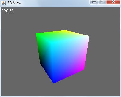
还行。
总结
目标达成。
我在代码中很多地方都注释了 // FIXME 需要透视校正,这些位置是要留给以后改造的。在顶点着色时还看不出来问题,但是到实现纹理采样时问题就大了。
不过这是以后要处理的问题,现在权且标记一下。